How to use Substation Trainer
This guide works like zooming in on a drawing. It starts with the whole site, then one station, then the systems inside that station, one circuit, one piece of equipment, and finally individual parts, clearances and safety distances. Each level builds on the one before it.
Plan on 45 to 60 minutes the first time through. Open the trainer in a second tab and do each Try it box as you reach it.
Before you start
- Browser: use a current Chrome or Microsoft Edge on a desktop or laptop. Edge has the most natural-sounding voices (Aria, Guy, Jenny), so use it if you want the spoken explanations.
- Mouse: a mouse with a scroll wheel makes moving around much easier than a trackpad.
- Nothing to install: the trainer runs in the browser. There is no login.
- Progress: lesson progress and your quality setting are saved in this browser on this computer. Another browser or computer starts fresh.
The whole site
Substation Trainer is a 3D model of nine complete substations. You can orbit and zoom each one, click any part to learn what it is, open the drawings side by side with the model, and practice real tasks such as switching, clearance checks and fault tracing. Equipment is modeled to typical US utility practice (IEEE, NESC, ANSI). It is a training model, not a construction drawing.
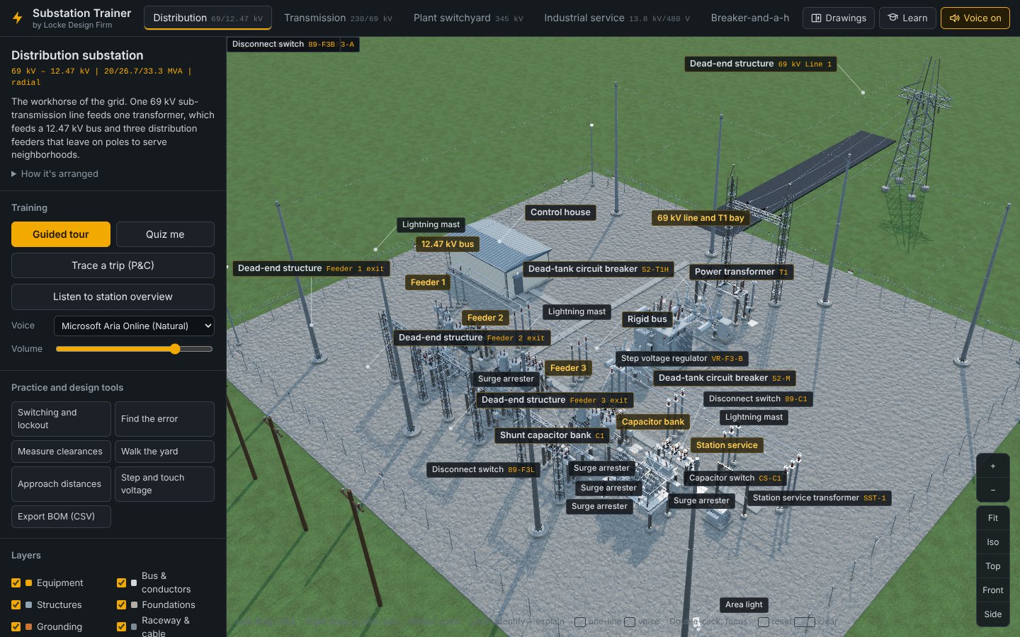
The four areas of the screen
| Area | What's in it |
|---|---|
| Header | The station tabs, plus three buttons on the right: Drawings opens the drawing pane, Learn opens lessons, the glossary and the certificate, and Voice on turns spoken explanations on or off. |
| Side panel | Top to bottom: the station name, ratings and description; Training (tour, quiz, trip trace, voice settings); Practice and design tools; Layers and display settings; and the searchable Component catalog. On a narrow screen it hides behind the ☰ button. |
| 3D view | The model with its labels. Zoom and view buttons sit on the right edge, and a strip of mouse hints runs along the bottom. |
| Drawing pane | Opens on the right when you press Drawings or O. The 3D view shrinks to make room. Covered at level 3. |
The nine stations
Each tab is a different kind of substation. They are listed in the order they appear. If you are new, start with Distribution, which is the simplest, then work up in voltage.
| Tab | Rating | What it teaches |
|---|---|---|
| Distribution | 69 – 12.47 kV, 20/26.7/33.3 MVA | The basic station: one line, one transformer, a 12.47 kV bus and three feeders with regulators, reclosers and a capacitor bank. |
| Box structure | 69 – 12.47 kV, 12/16/20 MVA | A low-profile station built on box structures. Switch the structure between galvanized steel and wood pole under the station description. |
| Transmission | 230 – 69 kV, 280 MVA auto | Two 230 kV lines on a main bus, an autotransformer, and a 69 kV bus that serves sub-transmission lines. |
| Plant switchyard | 345 kV, 420 MVA GSU | How a generating plant connects to the grid through a generator step-up transformer. |
| Industrial service | 13.8 kV – 480 V, 2500 kVA | A customer-owned service: pad-mounted transformer and 480 V switchgear. |
| Breaker-and-a-half | 500 kV, 1200 MVA auto | A bulk transmission switching station. Breaker-and-a-half comes close to the reliability of double-breaker double-bus at about 1.5 breakers per circuit. |
| Renewable collector | 230 – 34.5 kV, 166 MVA | A solar plant's substation: four collector feeders gathered onto one main power transformer. |
| GIS | 115 kV GIS, 2 × 50 MVA | Gas-insulated switchgear in SF6-filled enclosures, with 13.8 kV metal-clad gear. |
| Mobile | 69 – 12.47 kV, 25 MVA | A complete substation on a trailer, used for emergencies and planned outages. |
Try it
- Click through every station tab once. Each one takes a second or two to build.
- Read the short description at the top of the side panel for each.
- Come back to Distribution to continue.
One station
Pick one station and learn to move around it. Everything else in the trainer depends on getting the camera where you want it.
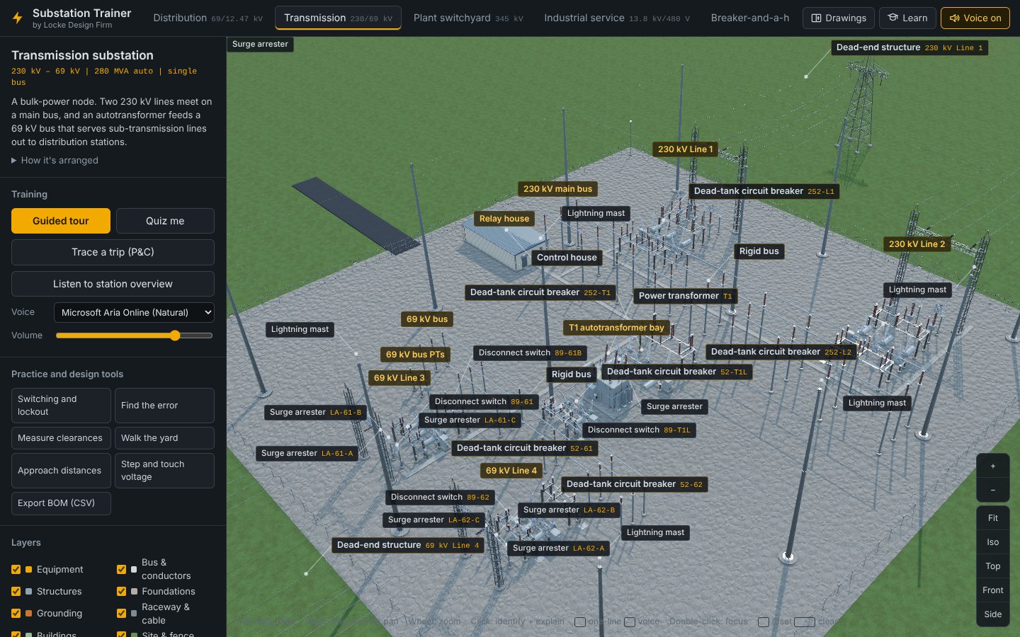
Mouse and keyboard
| Action | How |
|---|---|
| Orbit | Left-drag in the 3D view |
| Pan | Right-drag, or hold Shift and left-drag |
| Zoom | Mouse wheel, the + and − buttons, or the + and − keys |
| Focus on something | Double-click it. The camera flies to it and centers it. |
| Reset the camera | R |
| Clear a selection | Esc |
Standard views
The buttons on the right edge give you the views you would expect on a drawing set: Fit frames the whole station, Iso gives an isometric, Top a plan view, and Front and Side give elevations. Use Fit any time you get lost.
Labels change as you zoom
From far away, only big items are labeled: bays, buses, transformers, buildings and line terminations. As you zoom in, labels for smaller parts appear, such as bushings, terminal connectors, gas density monitors and cooling fans. Each label has a leader line to the part. Yellow labels name a bay or area. Dark labels name a component, and the tag number follows in amber (for example 52-T1H). Labels start off for a clean view. Turn them on with the Labels checkbox under Layers.
Know the station before you zoom in
- Open How it's arranged under the station description. It explains the bus arrangement, the path power takes through the station, and which code applies (NESC, NEC, NFPA 70E and so on).
- Press Listen to station overview to hear the same thing read aloud.
If the model feels slow
Under Layers, the Quality setting has three choices. High keeps full shading on while you move. Balanced (the default) draws full detail when the camera stops. Fast turns off shadows and ambient occlusion, and is the right choice for older laptops and the 500 kV station. Phones start on Fast automatically.
Try it
- On the Distribution tab, press Top, then Front, then Iso.
- Turn on Labels, then zoom slowly into the transformer with the wheel and watch smaller labels appear.
- Double-click a breaker to focus on it, then press R to reset.
The station's systems
A substation is several systems laid on top of each other: equipment, bus, structures, foundations, grounding, raceway, buildings and site work. This level shows you how to look at one system at a time, and how to read the drawings that describe them.
Layers
Each checkbox under Layers shows or hides one system: Equipment, Bus & conductors, Structures, Foundations, Grounding, Raceway & cable, Buildings and Site & fence. Turn off Equipment and Bus to see the steel alone, or show only Grounding and Foundations to study what is below grade.
X-ray
The X-ray checkbox makes the ground and crushed rock see-through, so you can see piers, the ground grid, ground rods and buried conduit in place under the yard.
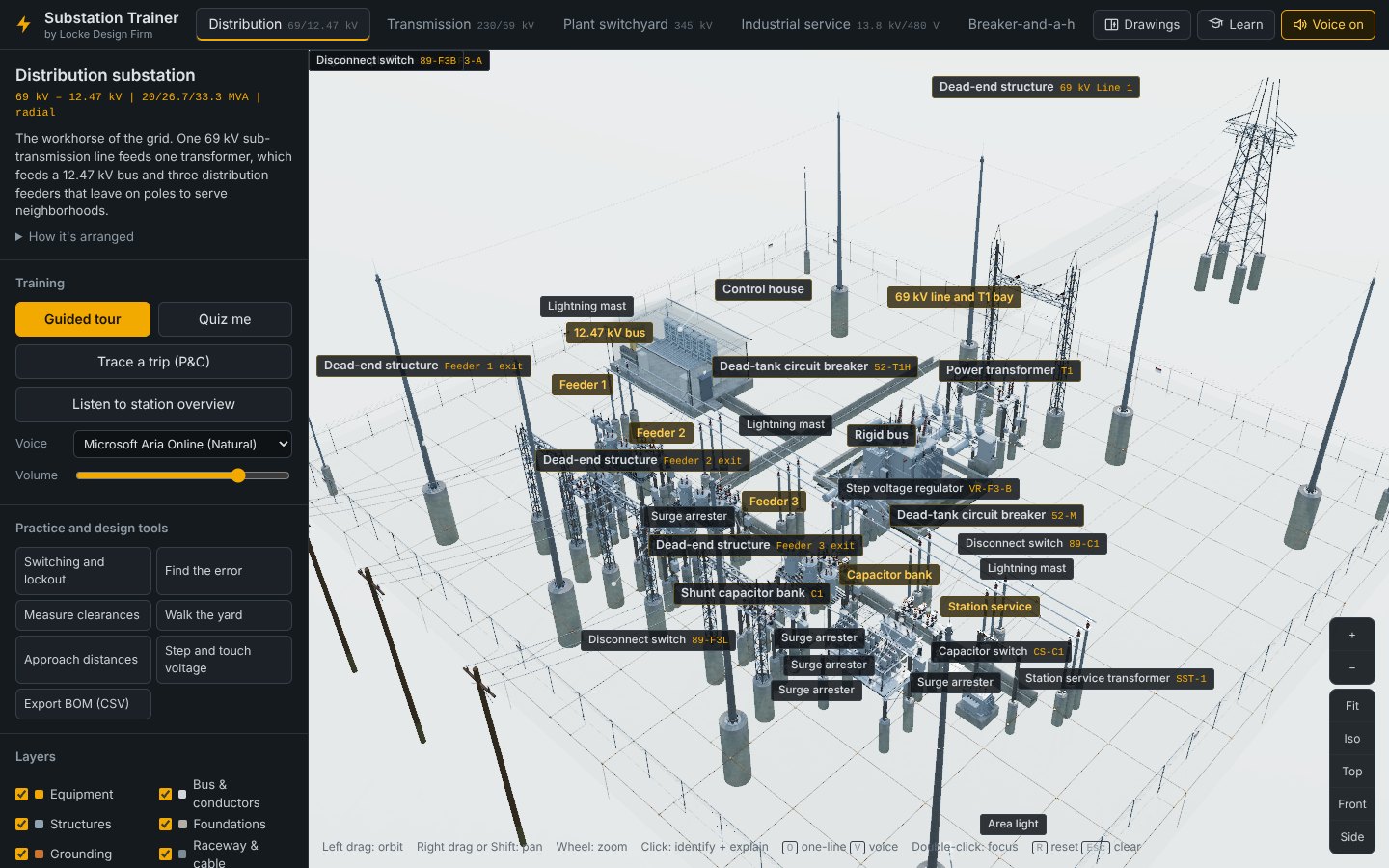
Component catalog
The catalog at the bottom of the side panel lists every type of component in the station, grouped by category, with the count next to each. Type in the search box (for example arrester, CT or ground) to filter it. Click an entry to highlight every one of that type in the yard and open its description.
The drawing set
Press Drawings or O to split the screen. The drawing opens on the right, linked to the model on the left:
- Click a symbol on the drawing and the trainer finds that equipment in the yard and highlights it.
- Click equipment in the yard and its symbol is highlighted on the drawing.
- Drag to pan the drawing, and use Fit, + and − to zoom. Pick the sheet from the dropdown at the top left of the pane.
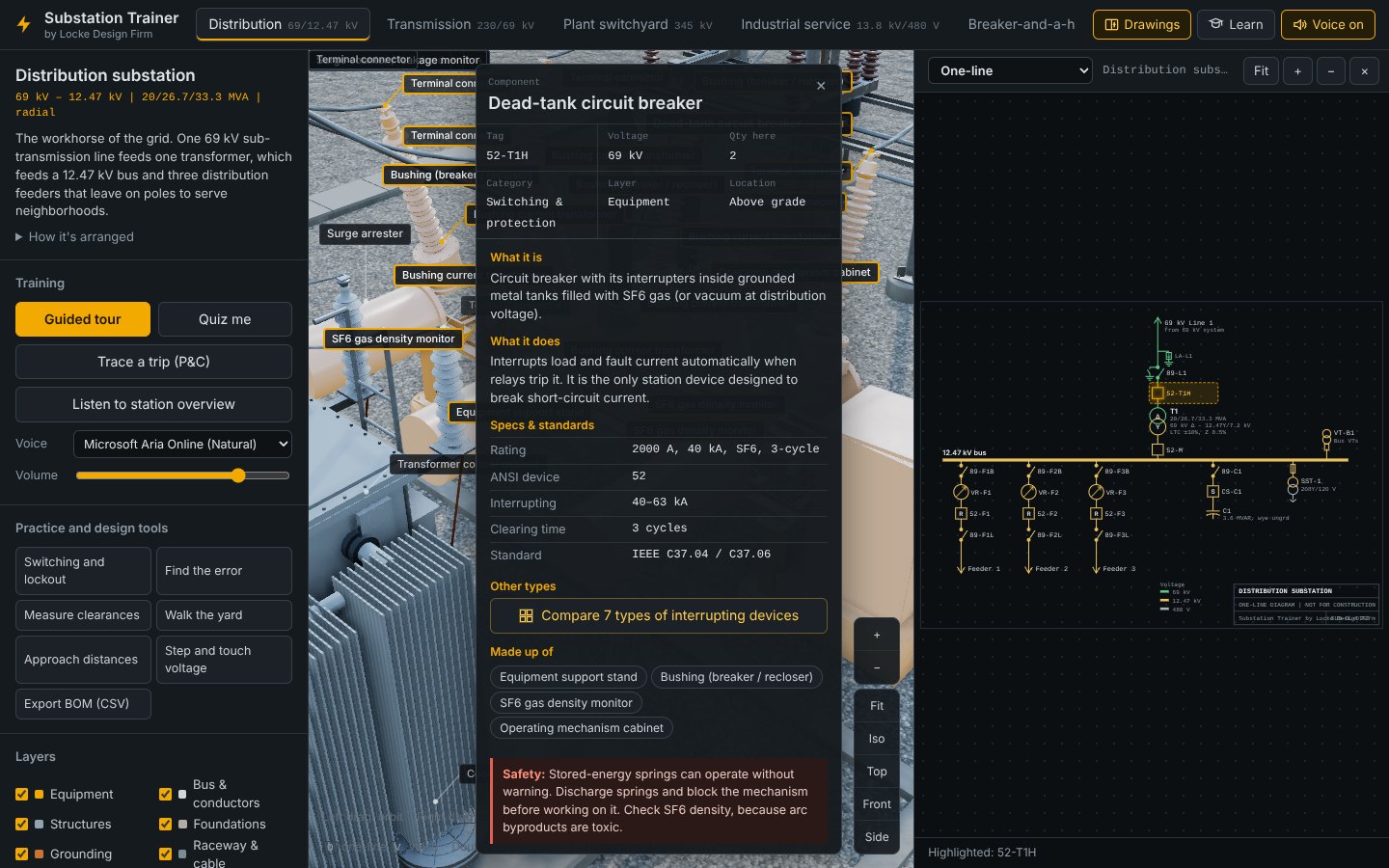
Every station has the same sheet list. Electrical sheets show how things connect; physical sheets show where things are.
| Sheet | What it shows |
|---|---|
| One-line | The power path, one line for all three phases. Start here. |
| Protection zones | Each relay zone as a dashed box. Zones overlap at the breakers so nothing is left unprotected. Click a zone to see what it covers. |
| Three-line | Each phase drawn separately: transformer winding connections, CTs on every phase, and grounding. |
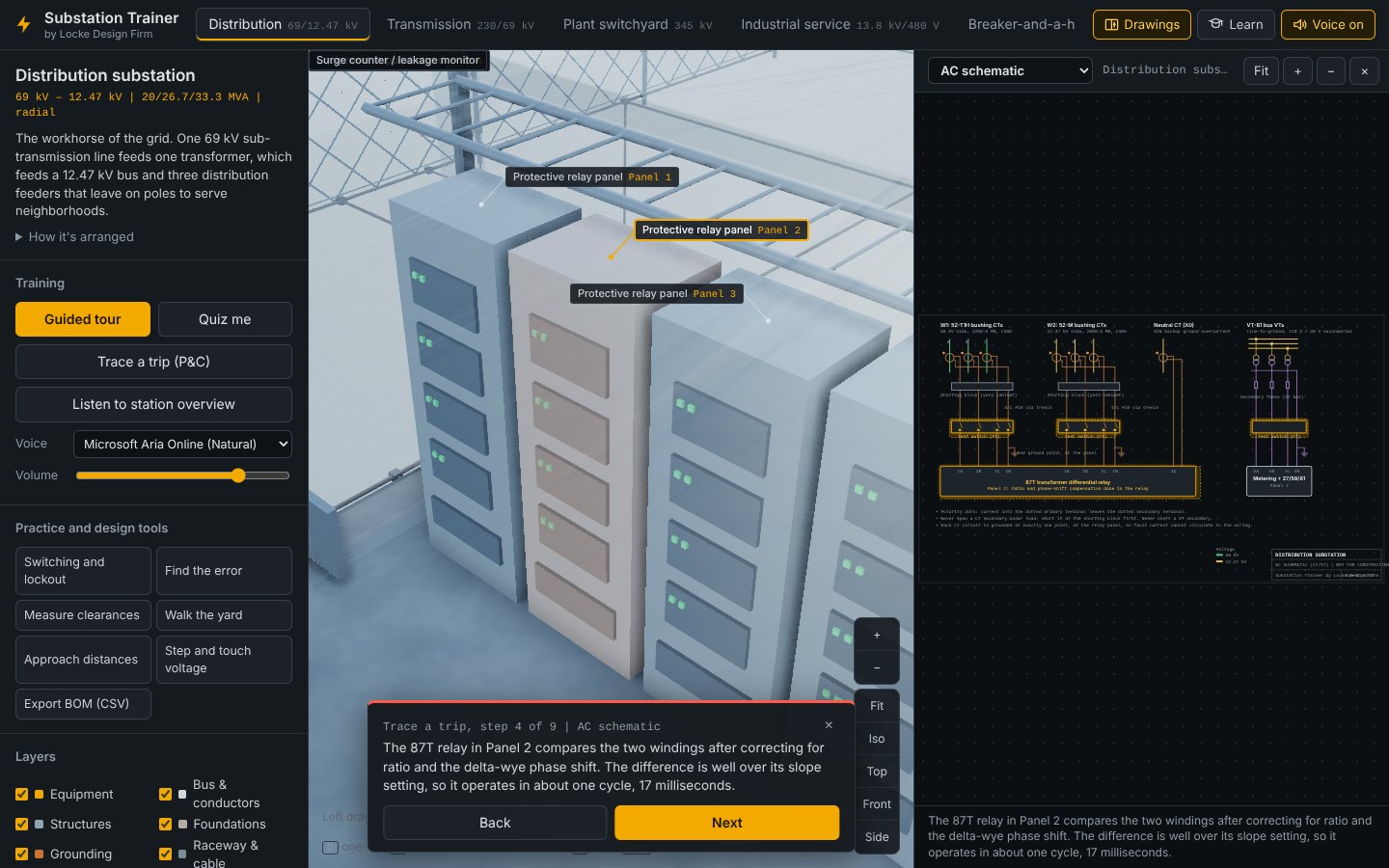
| AC schematic | CT and VT secondary wiring from the yard to the relays: polarity, shorting blocks, test switches and the single ground point. |
| DC schematic | The trip and close circuits as a ladder, (+) on top and (−) on the bottom. |
| Cable block | Every control cable from the yard device, through the trench, to its relay panel. |
| Relay panels | Front elevations of the panels in the control house: relays, lockouts, control switches and the DC system. |
| Bus configurations | A study comparing bus arrangements. Pick a scenario, then click a breaker, bus or circuit to see what stays in service. |
| Arrangement plan | Plan view of the whole yard drawn from the model, with grid coordinates and fence dimensions. |
| Section | An elevation cut through the main transformer bay: heights, foundations and ground grid depth. |
| Grounding plan | The buried grid, perimeter rods and every riser from equipment to the grid. |
| Conduit plan | Trench routes and every conduit run from a junction box to the trench, with elbows marked. |
| Foundation plan | Every pier and pad, with a schedule of types, quantities and concrete volume. |
| Lightning shielding | Rolling-sphere protected zones around masts and dead-end peaks, with every live point checked. |
Try it
- Turn on X-ray, zoom toward a breaker and find its pier and ground riser. Turn X-ray off.
- Press O. On the one-line, click the transformer symbol and watch the camera find T1.
- Switch the sheet to Grounding plan, then Foundation plan, and compare each to the model.
- Search the catalog for CT and click the result.
One circuit
Now follow one path through the station: power coming in, being transformed and going out, the relays that protect it, and the switching steps that make it safe to work on.
Guided tour
Press Guided tour. The camera flies to each stop in the order power flows, highlights the equipment and explains it. Use Back and Next to move through it at your own pace. With voice on, each stop is read aloud.
Trace a trip (P&C)
Press Trace a trip (P&C) to follow a fault from start to finish in six to ten steps, depending on the station. The trace places a fault in the yard, then steps through the CTs that see it, the AC schematic, the relay in the control house, the lockout, the DC trip circuit and the breakers that open. Each step changes the drawing on the right and the view on the left together, so you can see where each piece physically sits.
Switching and lockout
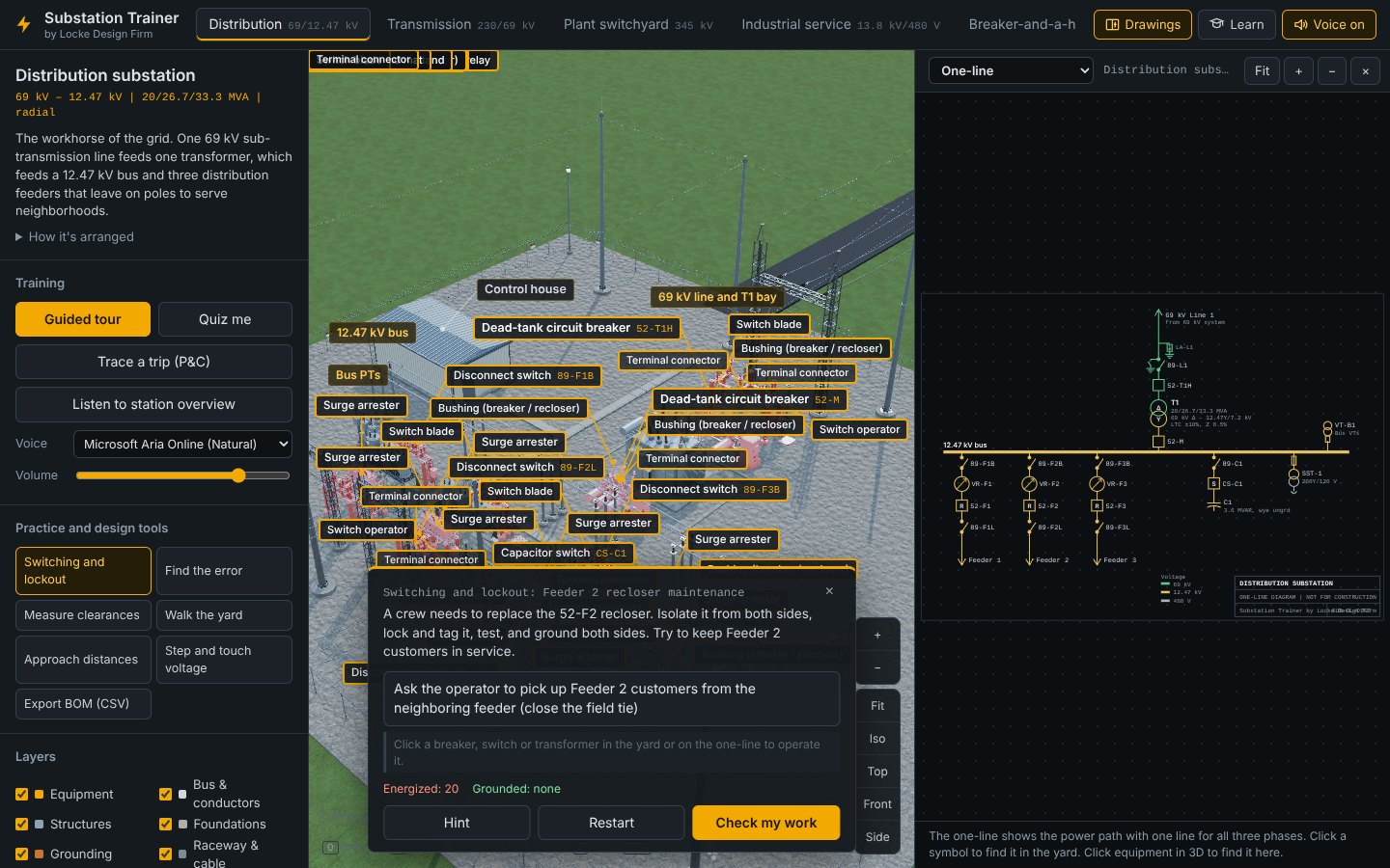
Press Switching and lockout and pick a clearance task. Most stations have two:
| Station | Tasks |
|---|---|
| Distribution | Feeder 2 recloser maintenance Take T1 out of service |
| Box structure | Feeder 2 recloser maintenance on bypass Take T1 out of service |
| Transmission | Take T1 out for maintenance 230 kV Line 1 clearance for a line crew |
| Plant switchyard | 352-G1 breaker maintenance 345 kV Line 2 clearance |
| Industrial service | De-energize the 480 V switchgear |
| Breaker-and-a-half | Breaker 5012 maintenance with no outage Clear 500 kV Line 1 |
| Renewable collector | Collector 3 breaker maintenance Take the main power transformer out |
| GIS | Take T1 out without dropping customers 115 kV Line 2 clearance |
| Mobile | Release the mobile so it can move |
Then do the clearance the way you would in the field:
- Click a breaker, switch or transformer, either in the yard or on the one-line. A menu opens with the actions for that device.
- Choose Open or Close, then Lock and tag each isolation point.
- Use Test for voltage on each side of the work, then Apply portable grounds or close a ground switch.
- Watch the Energized and Grounded counts at the bottom of the card.
- Press Check my work when you think the clearance is complete. Use Hint if you are stuck and Restart to start over.
Try it
- Run the Distribution guided tour to the end.
- Run Trace a trip and read each step against the drawing.
- Complete the Feeder 2 recloser clearance with as few hints as you can.
One piece of equipment
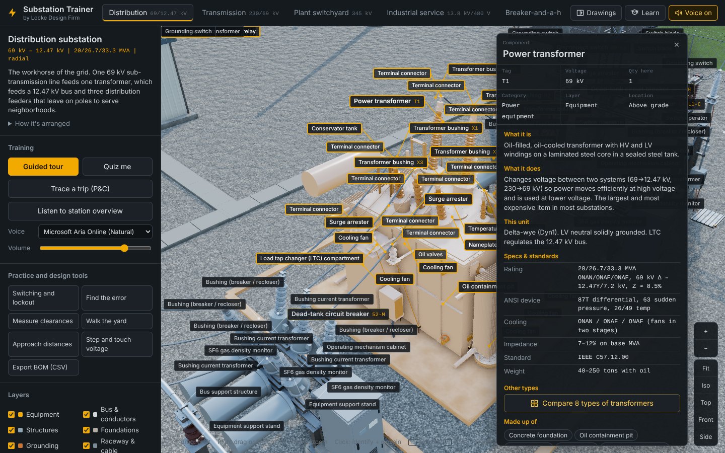
Click any part of the model. It is highlighted, its symbol lights up on the open drawing, and the info panel opens with everything the trainer knows about it. With voice on, a short spoken explanation starts, written for someone new to substations.
Reading the info panel
| Section | What it tells you |
|---|---|
| Header | Tag, voltage, how many are in this station, category, layer, and whether it is above or below grade. |
| What it is | A plain description of the equipment. |
| What it does | Its job in the station. |
| This unit | Notes specific to this one, such as winding connection or what it regulates. |
| Specs & standards | Ratings, ANSI device number, cooling, impedance and the governing standard. |
| Other types | Opens the type gallery (below). |
| Made up of | Its sub-parts. Click one to select it. |
| Safety | The hazard to know about before working on it. |
Panel buttons
- Listen reads the explanation aloud. Press it again (it changes to Stop) to stop.
- Focus flies the camera to the part. F does the same.
- Isolate hides everything else so you can orbit the part on its own. Show everything brings the station back.
- Highlight all lights up every part of the same type in the station.
Compare other types
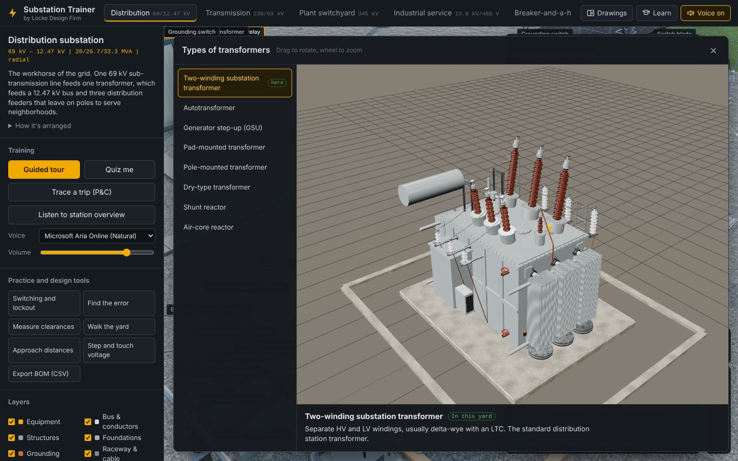
Press Compare … types to open a gallery of other designs that do the same job. For example, transformers include the substation two-winding unit, autotransformer, GSU, pad-mount, pole-mount, dry-type, shunt reactor and air-core reactor. The type used in this yard is tagged here. Drag to rotate the model and use the wheel to zoom.
Voice settings
Turn spoken explanations on or off with the Voice on button in the header or the V key. Choose a voice and set the volume under Training in the side panel. The trainer uses the voices built into your browser, so Microsoft Edge on Windows gives the most natural results.
Try it
- Click T1 and read every section of the panel.
- Press Isolate, orbit the transformer, then press Show everything.
- Open the transformer gallery and find the type used in the Plant switchyard (GSU).
- Click a surge arrester and press Highlight all.
Parts, clearances and safety
At the closest level you are checking dimensions and distances: how far a live part is from steel, from another phase, from the ground and from you. These are the tools a designer or a field worker uses to judge whether something is safe.
Measure clearances
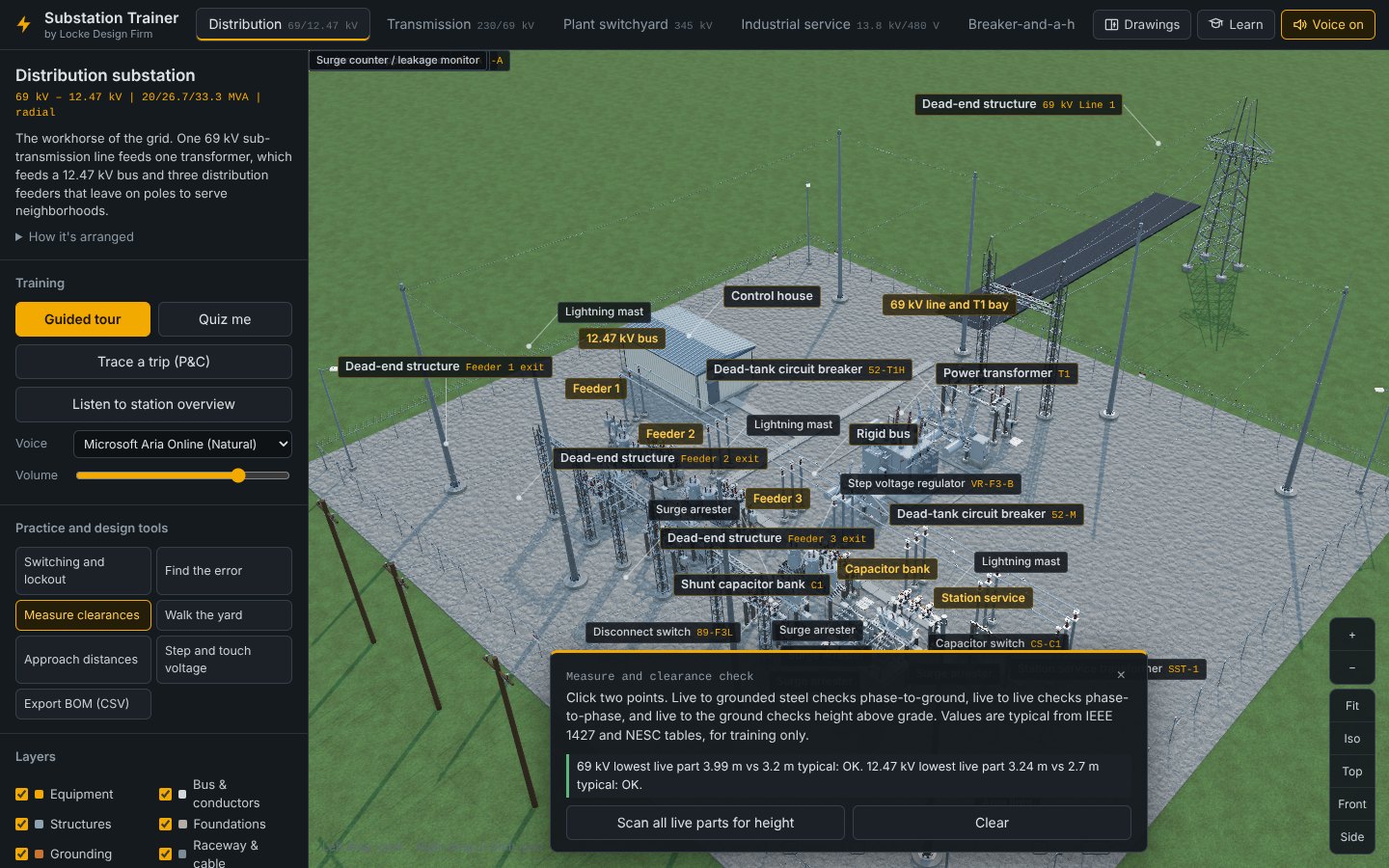
Press Measure clearances, then click two points in the model. What you click decides the check:
- Live part to grounded steel: phase-to-ground clearance.
- Live part to another live part: phase-to-phase clearance.
- Live part to the ground: height above grade.
The result is compared with typical values from IEEE 1427 and the NESC and marked OK or not. Scan all live parts for height checks the lowest live part at every voltage in one step. Clear removes your dimensions.
Approach distances
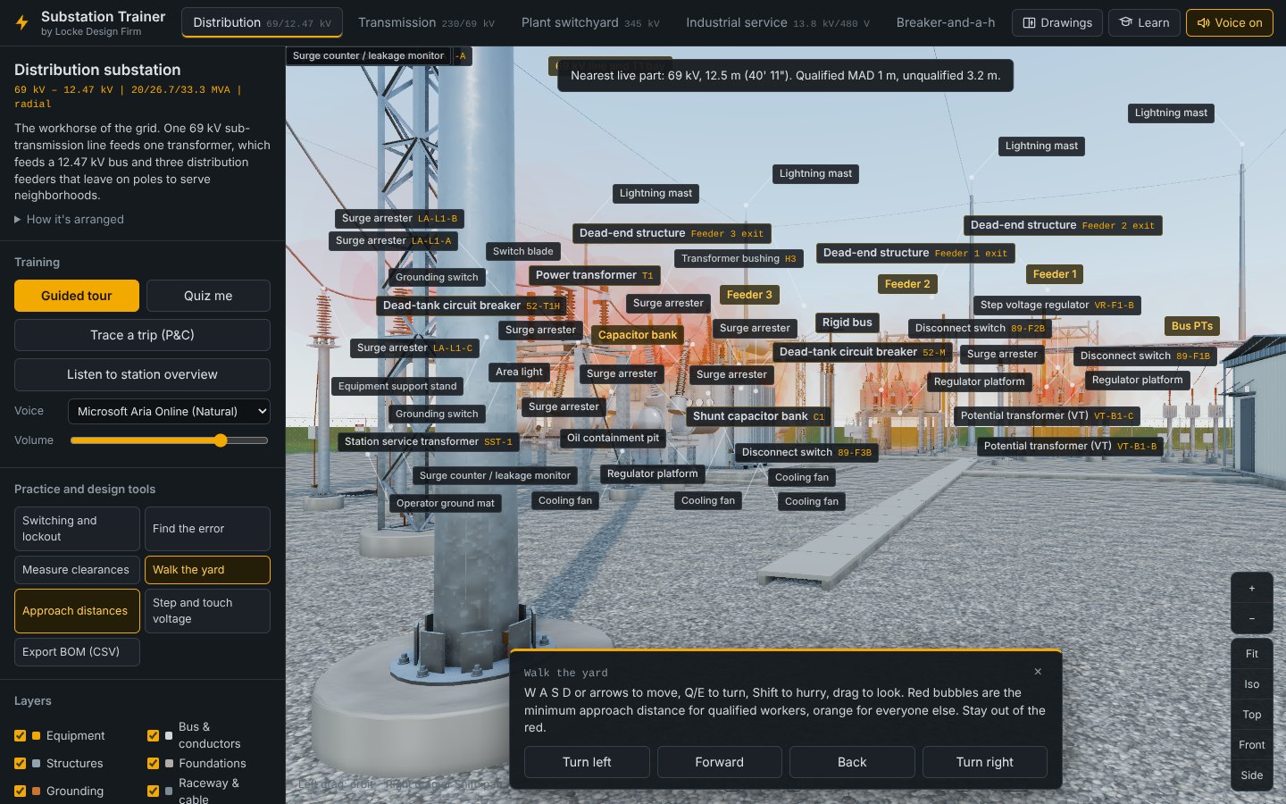
Approach distances is a toggle. It wraps every live part in bubbles: red is the minimum approach distance for qualified workers, and orange is the distance for everyone else. Leave it on while you walk the yard.
Walk the yard
Walk the yard puts you at eye level inside the fence. Move with W A S D or the arrow keys, turn with Q and E, hold Shift to move faster, and drag to look around. The on-screen buttons do the same. A readout at the top shows the nearest live part, its voltage, its distance and both approach distances. The screen warns you if you step inside the red.
Step and touch voltage
Step and touch voltage shows how the ground grid protects people during a ground fault, using a simplified IEEE 80 model. Choose a 70 kg or 50 kg body and the fault clearing time; the card shows every assumption behind the tolerable limits.
- Set the fault current and soil resistivity with the sliders.
- Turn the ground grid and crushed rock on and off to see what each contributes.
- Switch the color map between touch voltage, step voltage and ground surface potential.
- Hover over the yard to read the values at that spot, and click to move the fault.
The card reports grid resistance, ground potential rise, and the maximum touch and step voltages against the tolerable limits, including touch voltage on the fence from outside. It is for teaching, not a grounding study.
Arc flash
Arc flash calculates incident energy and the arc-flash boundary with the IEEE 1584-2002 equations. Pick a preset (480 V switchgear, a 480 V MCC, 13.8 kV metal-clad gear, a 12.47 kV open-air bay or 4.16 kV plant gear) or set the voltage, bolted fault current, clearing time, working distance and equipment type yourself. The card builds a sample NFPA 70E warning label. Turn on Maintenance switch to see how a faster instantaneous trip cuts the energy. It is a teaching model: real labels come from a study done in arc-flash software with the facility's actual data.
Find the error
Find the error plants up to five construction or design mistakes in the yard, such as a missing ground, sign or arrester. Walk it like a site inspection or a drawing review and click where something is wrong. The card counts what you have found and your wrong clicks. Reveal the rest shows what you missed, and New inspection plants a new set.
Try it
- Measure from a 12.47 kV bus to its support steel, then between two phases.
- Turn on Approach distances, walk the yard, and get as close to the transformer as you can without turning the screen red.
- In Step and touch voltage, turn off the crushed rock and watch the touch limit drop.
- Find every error in one inspection without revealing any.
- Open Arc flash, pick 480 V switchgear, and turn on the maintenance switch. Compare the incident energy.
Proving what you learned
The last level turns what you have done into a record: a quiz score, completed lessons, a printed certificate and, for designers, a material list from the model.
Quiz me
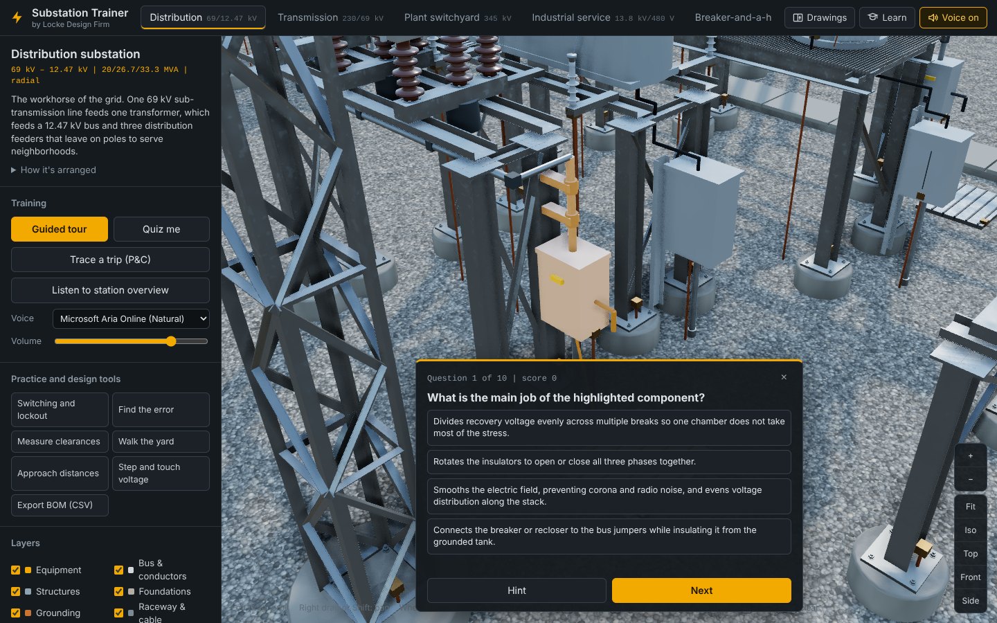
Quiz me asks ten questions about the station on screen. Some highlight a part and ask what it is; others ask what a part does. The answer choices are always similar items (four kinds of switching devices, four kinds of structures, and so on), so you have to know the difference rather than just recognize the category. Labels are hidden during the quiz. Press Hint if you need a nudge. A score of 8 or better counts toward the lessons.
Lessons
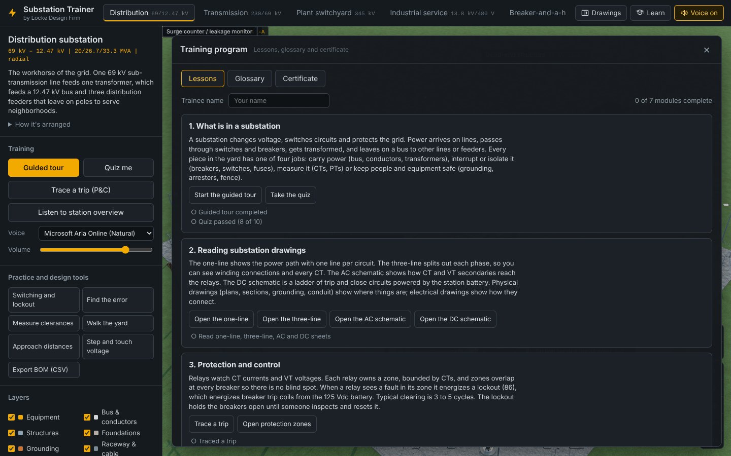
Press Learn in the header and enter the trainee's name. There are eight modules. Each has a short reading, buttons that take you straight to the right tool, and checkmarks that fill in when you finish the activity:
| Module | To complete it |
|---|---|
| 1. What is in a substation | Finish the guided tour, and score 8 of 10 on the quiz |
| 2. Reading substation drawings | Open the one-line, three-line, AC and DC sheets |
| 3. Protection and control | Trace a trip |
| 4. Switching and working safely | Pass a switching clearance, and walk the yard |
| 5. Grounding and lightning | Explore step and touch voltage, and read the grounding and shielding plans |
| 6. Design checks | Check three clearances, and find every error in an inspection |
| 7. Bus configurations | Compare three bus configurations in the bus study |
| 8. Arc flash and which code applies | Calculate an arc-flash label |
Glossary
The Glossary tab has ANSI device numbers (21, 50/51, 52, 86, 87 and the rest), common abbreviations (BIL, CCVT, GIS, GPR, GSU and others) and every component in the trainer. Type to search it.
Certificate
When all eight modules are complete, the Certificate tab lets you print a Substation Trainer certificate with the trainee's name. Until then it lists the modules that are left. Progress is saved in that browser only, and Reset my progress clears it, which is useful on a shared training computer.
Export BOM (CSV)
Export BOM (CSV) downloads a bill of materials for the station on screen, built from the model. It opens in Excel with these columns: Category, Item, Spec / rating, Qty, Unit and Tags. Along with the equipment, it includes ground grid conductor, ground rods and welds, conduit and elbows, trench, fence and crushed rock quantities. The quantities are representative of the training model, not a takeoff for a real project.
Export cable schedule (CSV) downloads the control cable schedule for the station: cable number, yard device, destination panel, function, conductor count and size, and an estimated length (route plus 10% plus 3 m slack). It uses the same cable assignments as the Cable block sheet.
Try it
- Take the quiz until you score 8 or better.
- Open Learn, enter your name, and see which checkmarks you already earned in levels 2 to 6.
- Export the Distribution BOM and open it in Excel.
Quick reference
Keyboard shortcuts
| Key | Does |
|---|---|
| O | Open or close the drawing pane |
| V | Voice on or off |
| R | Reset the camera |
| F | Focus on the selected part |
| + − | Zoom in or out |
| Esc | Leave the current tool, then clear the selection, stop the voice, or end the tour or quiz |
| W A S D / arrows | Move while walking the yard |
| Q E | Turn while walking the yard |
| Shift | Pan with left-drag, or move faster while walking |
A suggested plan for a new hire
| Session | Do this |
|---|---|
| 1 | Levels 1 and 2 of this guide. Tour the Distribution station, then look at every other tab. |
| 2 | Level 3. Read the one-line, three-line and grounding plan for Distribution against the model. Lesson modules 1 and 2. |
| 3 | Levels 4 and 5. Trace a trip, complete the Distribution switching task, and click through every major piece of equipment. Modules 3 and 4. |
| 4 | Level 6. Clearances, approach distances, step and touch voltage, find the error. Modules 5 and 6. |
| 5 | Repeat the switching task and quiz on the Transmission and Breaker-and-a-half stations, finish the bus study (module 7), and print the certificate. |
If something isn't working
| Problem | Fix |
|---|---|
| The model is slow or jerky | Set Quality to Fast, or turn off Shadows. The 500 kV station is the heaviest. |
| The voice sounds robotic, or "No voices found" | Open the trainer in Microsoft Edge and pick a voice with "Natural" in the name. |
| I'm lost in the model | Press Fit or R. |
| Clicking a part does nothing | Finish or close the quiz first, or press Esc to leave the current tool. |
| Something is missing from the yard | Check the Layers checkboxes, and press Show everything if a part is isolated. |
| My lesson progress is gone | Progress lives in the browser it was earned in. Use the same browser on the same computer. |